[Home] [Databases] [World Law] [Multidatabase Search] [Help] [Feedback] | ||
England and Wales High Court (Patents Court) Decisions |
||
You are here: BAILII >> Databases >> England and Wales High Court (Patents Court) Decisions >> Conversant Wireless Licensing SARL v Huawei Technologies Co., Ltd & Ors [2019] EWHC 1687 (Pat) (04 July 2019) URL: http://www.bailii.org/ew/cases/EWHC/Patents/2019/1687.html Cite as: [2019] EWHC 1687 (Pat) |
[New search] [Printable PDF version] [Help]
BUSINESS AND PROPERTY COURTS
INTELLECTUAL PROPERTY LIST (CHANCERY DIVISION)
PATENTS COURT
Fetter Lane, London, EC4A 1NL |
||
B e f o r e :
____________________
CONVERSANT WIRELESS LICENSING SARL |
Claimant |
|
- and - |
||
(1) HUAWEI TECHNOLOGIES CO., LIMITED (2) HUAWEI TECHNOLOGIES (UK) CO., LIMITED (3) ZTE CORPORATION (4) ZTE (UK) LIMITED |
Defendants |
____________________
Daniel Alexander QC and Miles Copeland (instructed by Allen & Overy LLP) for the First and Second Defendants and (instructed by Bristows LLP) for the Third and Fourth Defendants
Hearing dates: 14, 17-19, 21, 24 June 2019
____________________
Crown Copyright ©
MR JUSTICE ARNOLD :
Contents
Topic | Paragraphs |
Introduction | 1-2 |
The witnesses | 3-11 |
Prof Marshall | 3-7 |
Dr Brydon | 8-11 |
The skilled person | 12 |
Common general knowledge | 13-65 |
UMTS | 15-16 |
Basic network infrastructure in UMTS | 17-18 |
CDMA | 19-20 |
Duplexing | 21 |
Layers, protocols and stacks | 22-26 |
Transmission Time Interval | 27-30 |
HSDPA | 31-32 |
HSUPA | 33-35 |
E-DCH architecture | 36-39 |
E-TFCs | 40 |
Rise over Thermal | 41-44 |
Scheduled and non-scheduled grants | 45-50 |
The power headroom | 51 |
The minimum set | 52-53 |
HARQ | 54-61 |
E-TFC selection and E-DCH transmissions | 62-65 |
The Patent | 66-147 |
Field of the invention | 67-68 |
Description of the related art | 69-75 |
Summary of the invention | 76-90 |
Detailed description of the presently preferred embodiments | 91-147 |
The claims | 148-150 |
Construction | 151-167 |
[A] A method for autonomous uplink transmission | 152-155 |
[B] a virtual transmission time interval for a medium access control entity | 156-159 |
[B] which virtual transmission time interval defines a minimum time interval that is allowed between enhanced uplink transmissions | 160 |
[C] data packets | 161 |
[C] checking to determine whether the medium access control entity is transmitting data packets in a current air interface transmission time interval, by checking whether the medium access control entity is able to empty the radio link control buffer in the current air interface transmission time interval | 162-167 |
Essentiality | 168-205 |
Uplink DTX | 168-169 |
Uplink DRX | 170-179 |
Buffer Occupancy | 180-184 |
Retransmissions in Uplink DRX | 185-190 |
Conversant's case in outline | 191-194 |
Integer A | 191 |
Integer B | 192 |
Integer C and D | 193-194 |
Assessment | 195-205 |
Integer A | 195 |
Integer B | 196 |
Integer C | 197-205 |
Added matter | 206-227 |
The law | 206 |
Assessment | 207-209 |
Allegation 1 | 210-213 |
Allegation 2 | 214-215 |
Allegation 3 | 217-218 |
Allegation 4 | 219-226 |
Allegation 5 | 227 |
Obviousness | 228-258 |
Samsung | 229-244 |
The disclosure | 229-234 |
Obviousness | 235-245 |
Terry | 246-258 |
The disclosure | 246-25 |
Obviousness | 256-258 |
Insufficiency | 259 |
Summary of principal conclusions | 260 |
Introduction
The witnesses
Prof Marshall
Dr Brydon
The skilled person
Common general knowledge
UMTS
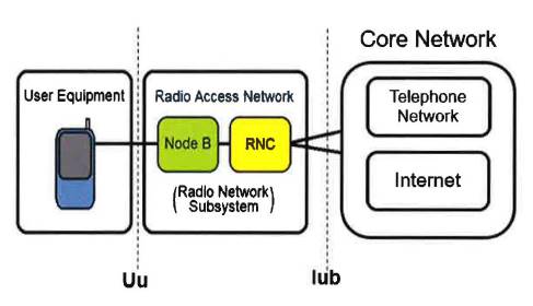
Basic network infrastructure in UMTS
CDMA
Duplexing
i) Frequency division duplexing (FDD), which allocates separate frequency bands to the uplink and downlink. Transmissions may then be sent simultaneously on the uplink and downlink.
ii) Time division duplexing (TDD), which enables uplink and downlink communications by time-division of transmissions on the same frequency band. In TDD, specific time slots are allocated for the UE to receive bursts of data on the downlink, and then to transmit a burst of data on the uplink.
Layers, protocols and stacks
i) Layer 1 is the physical layer (PHY), which is responsible for transmitting and receiving data over the airwaves. It maps transport channel formats specified by layer 2 onto physical channel formats which are the formats actually sent over the air. It is in the PHY that the processes of spreading and modulation are carried out.
ii) Layer 2 is the data link layer. It ensures there is a reliable flow of information across a communications link e.g. a radio link in UMTS. It consists of three sub-layers: the MAC, the Radio Link Control (RLC), which sits above the MAC; and the Packet Data Convergence Protocol (PDCP), which sits above the RLC. The RLC sends data to, and receives data from, higher layers and segments into, or reassembles it from, smaller RLC PDUs, of defined length. The RLC also buffers data for transmission. The MAC is responsible for mapping data from different services or logical channels onto transport channels for transmission by the PHY, and for multiplexing or demultiplexing higher layer PDUs into/from transport blocks to be sent to or received from the PHY.
iii) Layer 3 is the network layer. The function of this layer is to route packets across different networks.
Transmission Time Interval
HSDPA
i) The introduction of the 2 ms TTI (as mentioned above).
ii) The introduction of fast scheduling at the Node B. This transferred scheduling from the RNC to the Node B, allowing scheduling to be performed more quickly and responsively to the conditions on the air interface.
iii) The use of adaptive modulation and coding (AMC). This is a way of dynamically altering the modulation and/or coding used on the downlink to account for variation in signal quality. Importantly, the power of the downlink signal remains constant in respect of each UE (something that cannot be achieved on the uplink).
iv) Multi-code operation enabled multiple streams of data to be sent to a single UE or between multiple users each TTI by the use of spreading codes.
v) The introduction of HARQ retransmissions (as to which, see below).
HSUPA
i) The downlink is a one-to-many connection whereas the uplink is a many-to-one. This means that in the downlink power resource is centralised, whereas in the uplink it is not feasible to have transmissions at a constant power. The reason the 10 ms TTI was retained in HSUPA was to allow transmissions at lower power from power-limited UEs on the cell edge.
ii) In the downlink, transmissions are coordinated at the Node B, which is aware of the data that needs to be buffered and transmitted to each UE in the cell. In the uplink, transmissions are not coordinated: the network is not aware of the details of the data that each UE is generating, their power limitations etc, and none of the UEs are aware of each other at all.
iii) In the downlink, the transmissions to each UE are precisely synchronised, and hence the codes assigned to each UE are orthogonal to each other. This is not the case in the uplink, and therefore interference between the transmissions of different users is more problematic in the uplink (as explained below).
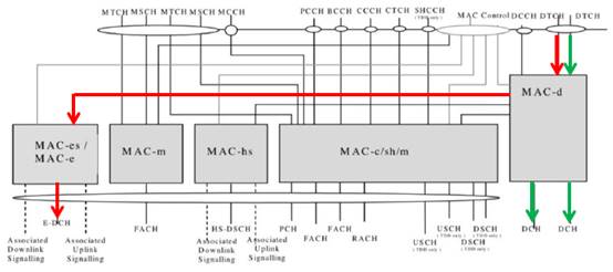
E-DCH architecture
E-TFCs
Rise over Thermal
Scheduled and non-scheduled grants
The power headroom
The minimum set
HARQ
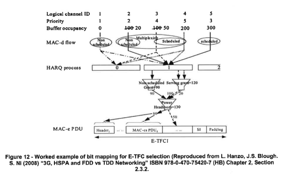
E-TFC selection and E-DCH transmissions
i) The MAC-e determines the scheduled and non-scheduled grants, and power headroom. These values feed into the process of multiplexing and E-TFC selection.
ii) The power headroom is used to determine the set of E-TFCs from which E-TFC selection may take place.
iii) The MAC-e identifies those flows for which there is available data and allocates that data, starting with the highest priority data. If there is no data for the highest priority flow, the MAC-e will consider the next highest priority, and so on. In this way the MAC-e allocates data up to the limits defined by the non-scheduled grant, scheduled grant and the power headroom.
iv) Based on the amount of data available, the MAC-e selects an available E-TFC format. The standards specify that the MAC-e will select the E-TFC format that will result in the minimum amount of padding.
v) The "multiplexing and TSN setting" entity then constructs a MAC-e PDU. One or several MAC-d PDUs from a particular MAC-d flow may be multiplexed into a MAC-es PDU, to which a MAC-es header is added. Several MAC-es PDUs and their headers may then be concatenated into a MAC-e PDU.
The Patent
Field of the invention
Description of the related art
Summary of the invention
"This control defines a minimum time interval between subsequent new transmissions. The control has no impact on retransmissions, which are performed normally."
It is common ground that "subsequent" here means successive.
" the application does not deliver SDUs to the MAC layer at a higher rate than that specified by the parameter. If the data source produces several packets in this time interval, the packets are grouped into a single SDU".
The skilled reader would understand from this that RLC SDUs are slowed down somewhere above the MAC layer, therefore affecting the subsequent flow of MAC-e PDUs into the PHY. It is then said that grouping the packets in the MAC layer enables the packet headers to be optimised and so more efficiently to share the uplink power resource between users.
"Alternatively, it is possible to introduce a new MAC parameter in the MAC-d layer. In the preferred embodiment, the new parameter is a 'virtual TTI' that defines the minimum time interval between subsequent new transmissions for a MAC-d flow. A first transmission would be permitted only once, during the virtual TTI. The virtual TTI could be signaled to the UE by the radio network controller (RNC). The UE could then implement the virtual TTI in the MAC-d layer. ."
Detailed description of the presently preferred embodiments
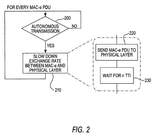
"For every MAC-e PDU, a check is made to determine whether the transmission is autonomous, as indicated in step 200. If the transmission is not autonomous, a check is continually performed until an autonomous transmission occurs, that is the method continues in a loop. If an autonomous transmission is detected, then the exchange rate between the MAC-e and the physical layer (layer one) is slowed down, i.e. the exchange rate is decelerated, as indicated in step 210. In accordance with the invention, the slow down of the exchange rate between the MAC-e and the physical layer occurs when the MAC-e layer sends a MAC-e PDU to the layer one (i.e., the physical layer), as indicated in step 220. The MAC-e PDU is sent to the physical layer every n*TTI, instead of once every transmission time interval (TTl), as indicated in step 230."
"With reference to FIG. 3, for a 10 ms air interface TTI of 10 ms, 2 VoIP packets (i.e., 1 RLC SDU) are transmitted every 40ms. In this case, a single VoIP packet is transmitted from the source every 20 ms. That is, the data source produces several (i.e. two) data packets within the 40 ms SDU inter-arrival rate that are grouped into a single SDU. One retransmission is shown for RLC SDUs #1 and #2, both containing 2 VoIP packets. "
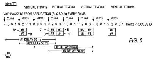
"With reference to FIG. 5, VoIP packets are transmitted every 20 ms. With a 40ms virtual TTI in MAC-d, 2 VoIP packets are transmitted in the same air interface TTI every 40 ms. In this case, a single packet is transmitted from the source every 20 ms and each RLC SDU contains one VoIP packet. That is, RLC SDUs, each containing a single VoIP packet, are delivered from the application to MAC every 20 ms. Here packets [sic] #1 (A) and packets [sic] #2 (B) are delivered to MAC layer in their own separate RLC SDUs with a 20 ms time difference, and grouped at MAC-d layer for transmittal in the same single 10 ms air interface TTI."
"The subsequent new packets #3 and #4 are grouped together in MAC-d for transmittal in the same 10 ms air interface TTI, because the 40 ms virtual TTI prevents this transmission before 40 ms after the start of the previous transmission has elapsed. The packets #1 (A) and #2 (B) are retransmitted (C and D). The packet #1 (A) is transmitted from the source 20 ms earlier than packet #2 (B), but is not allowed to be transmitted before the 40 ms virtual TTI has elapsed after the start of the previous packet first transmission."
"Additionally, it is possible to take into account the 'virtual TTl' in the application layer to optimize the protocol header overhead, as discussed below. Defining the parameter in the MAC layer advantageously supports the elimination of the dependency on the radio access network, as compared to the case where the transmission interval is defined in the PDP context/RAB parameter. If several radio bearers (RB) are multiplexed into the same transport channel, it should be possible to separately define a 'virtual TTl' for each RB."
"In accordance with the present contemplated embodiments, the UE power limitations in bad radio conditions, such as the UE running out of transmission power, are taken into account so that it then becomes possible to send a single speech packet per air interface TTI of 2 ms or 10 ms. Here, the MAC-d would check the RLC buffer of the UE once per virtual TTI, i.e., at the same interval as a normal TTI . As a result, packets received during the virtual TTI would be buffered at the RLC level.
In addition, the MAC is permitted to check the RLC buffer more frequently in certain special cases, such as when it is not possible to clear the RLC buffer due to power limitations, the transmission of higher priority packets from other RLC buffer[s] (e.g. SRB) or if there are bigger RLC SDUs (e.g., non-compressed headers or real time control protocol (RTCP) packets) that cannot be transmitted within one air interface TTI."
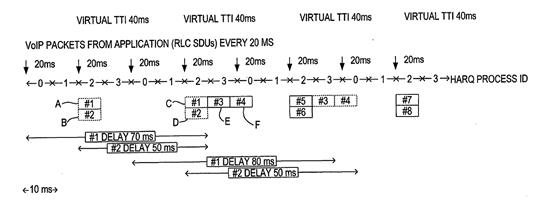
"With reference to FIG. 7, for a 10 ms air interface and a virtual TTI of 40 ms, two VoIP packets are transmitted every 40 ms. Here, packets #1 (A) and packets #2 (B) are grouped together into a single SDU since the subsequent new packet #2 (B) is transmitted within the 40 ms time period. A single transmission for packets #1 (C) and #2 (D) and #3 (E) and #4 (F) is shown. However, it is not possible to transmit subsequent new packets #3 (E) and #4 (F) during a single TTI. As a result, these packets are grouped together and transmitted in separate TTIs."
"Examples of the operation of the UE MAC under such conditions are as follows: (i) if the MAC is able to empty the RLC buffer during this air interface TTI, then the MAC will check the RLC buffer at the next predetermined subsequent time interval after the virtual TTI; (ii) if the MAC is not able to empty the buffer, then the MAC will also check the RLC buffer for the next air interface TTI. This permits rapid clearing of the RLC buffers when required, i.e., when large SDUs are utilized. However, the frequency of transmissions during normal operation remains limited.
In certain embodiments, the implementation of the present contemplated embodiment is permitted based on the configuration of the network, e.g., the network is configured to restrict the transmissions only to instances of times that are established by the virtual TTI or the network is configured to permit the above previously described operations."
"The present invention advantageously conserves control overhead. Specifically, the downlink E-DCH HARQ Indicator Channel (HICH) (i.e., the HARQ ACK/NAK is sent on E-HICH) overhead can be reduced because ACK/NAKs are needed less frequently. Also, the E-DCH dedicated physical control channel (E-DPCCH) overhead is reduced. In addition, a further savings [sic] in overhead is possible if the uplink dedicated physical control channel (UL DPCCH) gating is introduced. In this case, the DPCCH is not transmitted continuously but only when other UL channels are transmitted. In addition to the savings in system capacity, another advantage of the present invention is that battery power of the UE is conserved, since the UE needs to transmit and receive less often when a virtual TTl is used."
The claims
"[A] A method which is executed by a mobile station for autonomous enhanced uplink transmission in which a scheduling grant from a network is not required, comprising:
[B] determining a virtual transmission time interval for a medium access control entity, which virtual transmission time interval defines a minimum time interval that is allowed between enhanced uplink transmissions;
[C] checking to determine whether the medium access control entity is transmitting data packets in a current air interface transmission time interval, by checking whether the medium access control entity is able to empty the radio link control buffer in the current air interface transmission time interval;
[D] and for the case where it is determined that the medium access control entity is not transmitting in the current air interface transmission time interval, transmitting a next data packet only after a period determined by the virtual transmission time interval is determined to have elapsed."
"The method of claim 1, wherein determining the virtual transmission time interval comprises receiving from a network element the virtual transmission time interval."
Construction
[A] A method for autonomous enhanced uplink transmission
[B] a virtual transmission time interval for a medium access control entity
[B] which virtual transmission time interval defines a minimum time interval that is allowed between enhanced uplink transmissions
[C] data packets
[C] checking to determine whether the medium access control entity is transmitting data packets in a current air interface transmission time interval, by checking whether the medium access control entity is able to empty the radio link control buffer in the current air interface transmission time interval
Essentiality
Uplink DTX
Uplink DRX
"In FDD, for each Activated Uplink Frequency, in case the DTX feature is configured by higher layers and no E-DCH transmission is performed in this TTI on that Activated Uplink Frequency:
- if MAC Inactivity Threshold > 1 and no E-DCH transmission has been performed for MAC Inactivity Threshold - 1 previous TTIs or,
- if MAC Inactivity Threshold = 1:
- E-TFC selection shall only be performed for the TTIs where the following conditions are fulfilled:
- For 2ms TTI: [5*CFN + subframe number - UE DTX DRX Offset] mod MAC DTX Cycle = 0;
- For 10ms TTI: [5*CFN - UE DTX DRX Offset] mod MAC DTX Cycle = 0.
i) The CFN (Connection Frame Number) and subframe numbers are numbers which are assigned sequentially to identify a particular frame and subframe. The UE DTX DRX Offset is a parameter which is set by the network in effect to space when the respective MAC DTX cycles of different UEs allow transmissions to occur.
ii) Thus for a 2ms TTI, E-DCH transmissions are only allowed when (5 * current Connection Frame Number UE DTX DRX Offset + current subframe) is an integer multiple of MAC DTX cycle. This is because the mod operator finds the remainder after division of one number by another.
Buffer Occupancy
Retransmissions in Uplink DRX
"Whenever the UE transmits one E-DCH TTI the UE can use subsequent TTIs for E-DCH transmission as long as its transmission is continued (re-started) within UE_Inactivity_Threshold TTIs, and in addition the pending retransmissions can be done in the corresponding HARQ processes (retransmission times are not impacted by the inactivity threshold)."
Conversant's case in outline
i) If the reported buffer occupancy is not zero, then the E-TFC selection entity will indicate to the HARQ entity that there is a need for a new transmission. As a result, data will be pulled down from the RLC buffer, a MAC-e PDU will be constructed, and sent on to PHY. The MAC therefore determines that it will transmit a MAC-e PDU in this TTI by reference to the buffer occupancy.
ii) If, however, the buffer occupancy is zero, then the E-TFC selection entity will not indicate the need for a new transmission, so no data will be pulled down from the RLC buffer, and no MAC-e PDU be constructed or sent on to the PHY. The MAC therefore determines that it will not transmit a MAC-e PDU in this TTI by reference to the buffer occupancy. Because of this, no E-DCH transmission is performed in that TTI, and the restriction under section 11.8.1.4 will kick in. The MAC will therefore be unable to transmit a new MAC-e PDU on the E-DCH, until after the period determined by the MAC DTX cycle has elapsed.
Assessment
Added matter
The law
Assessment
"For example, it is expressly intended that all combinations of those elements and/or method steps which perform substantially the same function in substantially the same way to achieve the same results are within the scope of the invention. Moreover, it should be recognized that structures and/or elements and/or method steps shown and/or described in connection with any disclosed form or embodiment of the invention may be incorporated in any other disclosed or described or suggested form or embodiment as a general matter of design choice."
Obviousness
Samsung
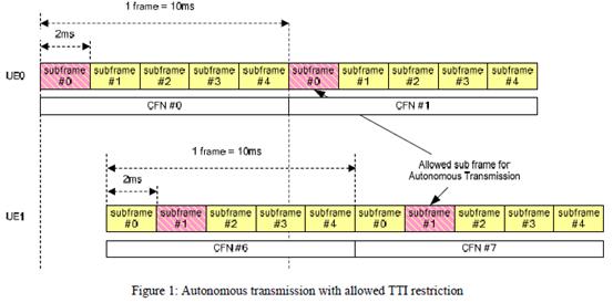
"Samsung addresses the same problem as the Patent and proposes a method for reducing the rate at which autonomous transmissions are made, in order to reduce their impact on uplink resources, which uses the same principle as the Patent. The Samsung approach is to undertake autonomous transmissions in a fixed cycle of sub-frames. It therefore imposes a 'minimum time interval' specifically between autonomous transmissions, which is the same concept as disclosed in the Patent."
Terry
Insufficiency
Summary of principal conclusions
i) at least claim 1 of the Patent is essential to Uplink DRX, and therefore the Defendants have infringed at least claim 1 if it is valid; but
ii) the granted claims are invalid for added matter, and the proposed amendment does not cure the invalidity, on the fourth ground advanced by the Defendants (but not on any of the other grounds); although
iii) the claims are not obvious over either Samsung or Terry; and
iv) the claims are not insufficient.